Add ZTP / Static device
This menu serves two specific purposes: pre-provisioning devices for Zero Touch Provisioning (ZTP) or adding "Static" devices to the map that cannot be managed via the standard AutoDiscovery process.
Confusion Alert: Which menu to use?
- Use "AutoDiscovery > Add entry" if: The device exists, is reachable via SSH, and you want Avalon to fully manage it.
- Use this page ("Add ZTP / Manual") if:
- The device is not yet online (ZTP Staging).
- The device is unreachable or incompatible with SSH (e.g., an unmanaged switch, an ISP router, or a passive tap) but you need to represent it visually on the topology.
Configuration parameters
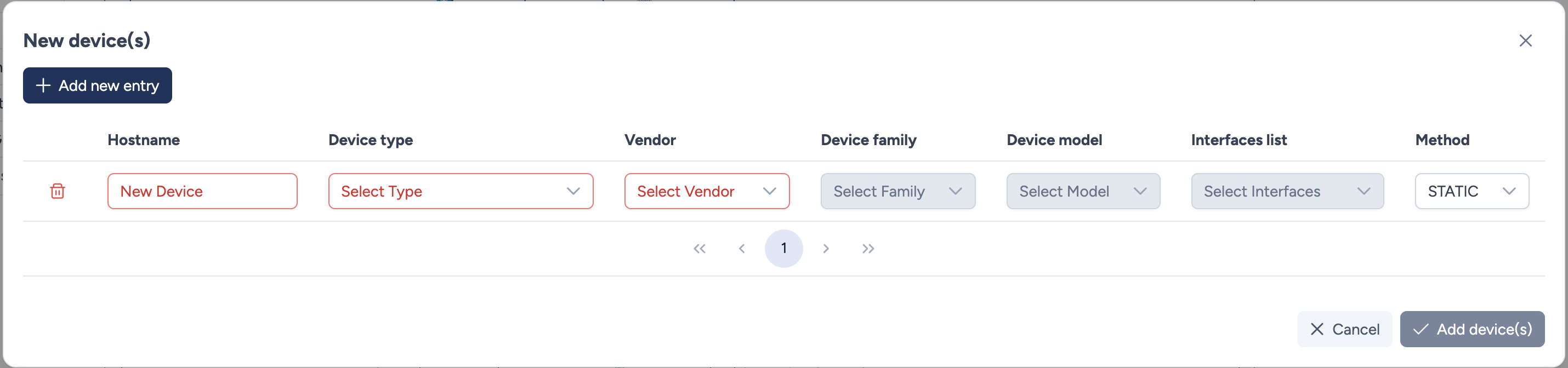
You can add multiple devices at once. For each entry, the following fields are required:
- Hostname: The label that will appear on the map.
- Device Type: Choose the standard Avalon category (e.g.,
router,firewall) to determine the icon style. - Vendor / Device family / Device model:
- These dropdowns allow you to specify the exact hardware identity.
- Prerequisite: These values must already exist in the global Inventory database. If the specific model you are looking for is missing, you must create it first in the Inventory > Models menu.
- Interfaces list:
- Defines the set of ports available on the device icon (crucial for manually drawing links on Static devices).
- Like models, this list must be pre-configured if the template does not already exist.
- Method: Defines the lifecycle of the device:
- STATIC: The device is passive. It will never be polled or managed by Avalon. It exists solely for documentation and visual topology purposes.
- ZTP: The device is currently offline but is expected to contact Avalon for provisioning. Once onboarded, it will become a managed device.
Where is my device?
Upon clicking Add device(s), the new icons will appear in the top-left corner of the topology canvas. You may need to drag them to their correct position on the map.
Actions
- Add new entry: Creates a blank line to define another device in the same batch.
- Trash icon: Removes the specific line from the list.
- Cancel: Returns to the dashboard without saving.
- Add device(s): Validates and creates all listed devices on the map.
Manually linking devices
Since "Static" devices are not polled by the AutoDiscovery engine, Avalon cannot automatically detect their neighbors. You must therefore manually define the cabling on the map.
Example Scenario:
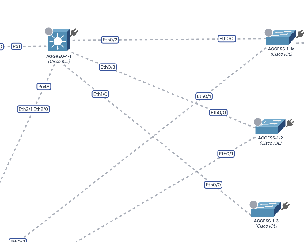
In this example, we have positioned the new switch ACCESS-1-3 into the "B1" area and we want to uplink it to the distribution switch AGGREG-1-1.
Step 1: Draw the connection
- Hover over the source device (
ACCESS-1-3). - Click and hold the Plug icon located at the top-right corner of the device.
- Drag the connection line towards the target device (
AGGREG-1-1). - Release the mouse button when hovering over the target.
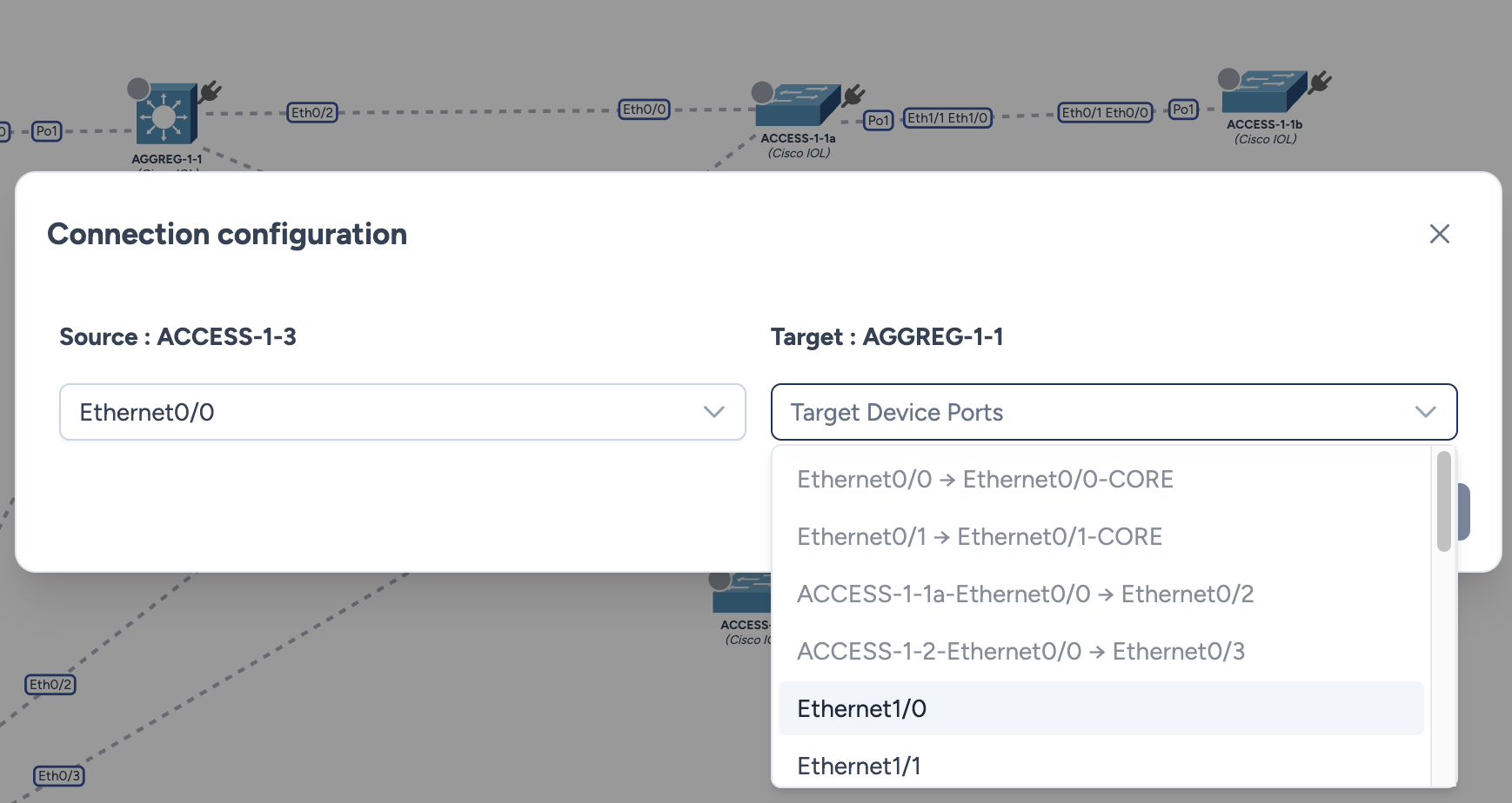
Step 2: Port Configuration
Upon releasing the link, a configuration modal appears to map the physical interfaces.
- Source Port: Select the interface on the newly created device (e.g.,
Ethernet0/0). - Target Port: Select the destination interface on the upstream device.
- Availability Check: Avalon automatically greys out and disables ports that are already occupied by another link, preventing cabling conflicts.
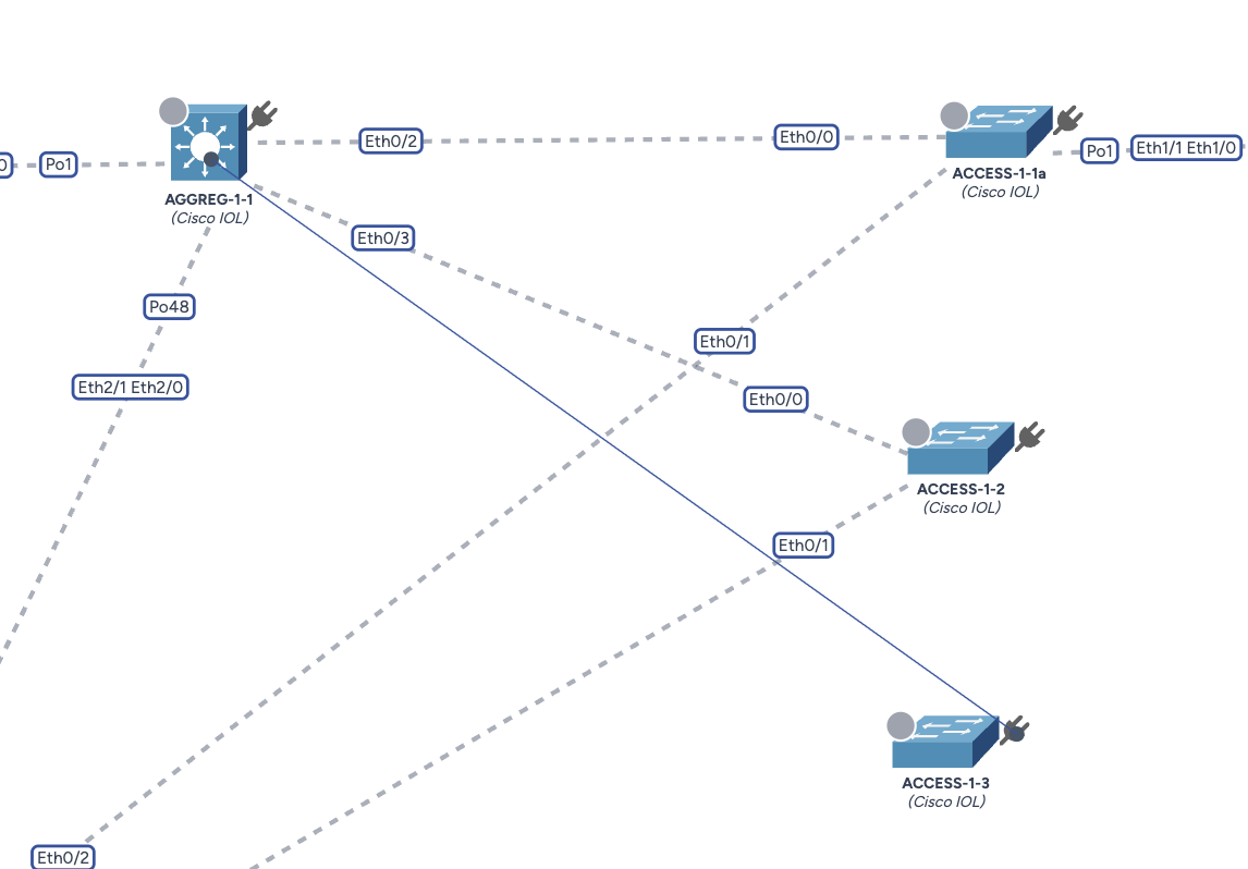
Step 3: Validation
Once saved, the link is immediately rendered on the topology.